How to interpret Acceptance Criteria for Ultrasonic Testing as per AWS D1.1
The Requirements of Ultrasonic Flaw detector equipment as per AWS D1.1 Structural Steel Welding code is given below:
Equipment:
The ultrasonic equipment’s shall be pulse echo type ‘A’ scan suitable for use with transducers oscillating at frequencies between 1&6 MHz. The equipment shall have valid calibration certificate .The test equipment shall have a calibrated gain control adjustable in discrete 1 or 2 Db steps over a range of at least 60Db.
Probe:
Transducers/ search units with following characteristics shall be used.
Angle beam: 70° ,60°,45° (within plus minus 2°).
Crystal Size: Crystal size shall be square or rectangular in shape and may vary from 5/8 inch to 1 inch (15mm to 25mm) in width and from 5/8 inch to 13/16 inch (15mm to 20mm) in height. The maximum width to height ratio shall be 1.2 to 1.0 and the minimum width to height ratio shall be 1.0 to 1.0.
Frequency:
The nominal probe frequencies shall be between 2 to 2.5 MHz inclusive. Other probe frequencies may be used if material variable such as material grain structure or size dictates.
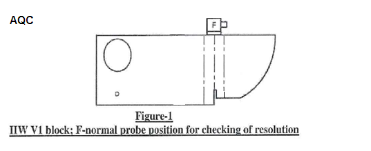
Normal (straight)beam :
Transducers shall have an active an active area of not less than ½ inch2 (323mm⁰)not more than 1 inch2 (645mm2).The transducer shall be round or square. Transducers shall be capable of proving resolution using 3 reflections from IIW V1 Block, as shown below:
Coupling Medium
Polycell jelly, grease, water or equivalent that shall provide satisfactory transmission of Ultrasonic sound waves.
Surface Condition
Scanning Surface shall be free of weld spatters surface irregularities or foreign materials that might interfere with the scanning during examination.
Calibration for Testing
7.1. All calibrations and tests shall be made with the reject (Clipping or suppression) control turned off. Use of the reject (Clipping or suppression) control may alter the amplitude linearity of the instrument and invalidate test results.
7.2.Calibration for sensitivity and horizontal sweep (distance) shall be made by the ultrasonic operator just prior to and at the location of testing of each weld.
7.3. Recalibration shall be made after a change of operators, each 30 minute maximum time interval, or when the electrical circuitry is disturbed in any way, which includes the following :
(1) Transducer change
(2) Battery change
(3) Electrical outlet change
(4) Coaxial cable change
(5) Power outage (failure).
Reference Level:
Reference level is the dB required to make peak reflection off ø 1.5mm (0.060″ ) side drilled hole SDH to 50% Full screen Height FSH.
Indication rating method:
The transducer shall be set in the position of IIW so that the
maximum reflection from 1.5 mm hole is received. The maximized signal shall then be adjusted to attain a horizontal reference line height indication.
The maximum decibel reading shall be used as the reference level, “b” in the calculation of the indication rating.
Indication rating, d =a-b-c
Where “a” – Instrument reading in decibels, when the indication from the discontinuity is adjusted to the amplitude source as the indication from 1.59mm φ hole at primary reference level.
“c” – Attenuation factor is attained by subtracting 1 inch (25mm) from the sound – path distance and multiplying the remainder by ⁰. The factor shall be rounded out to the nearest dB value.
Example 1 :
Case: UT carried out on welded plates of Material Thickness 10mm, cyclically loaded structure.
- Reference dB level is set to make peak reflection off ø 1.5mm (0.060″ ) side drilled hole to 50% Full FSH.
- Reference level noted is 65 dB,
- Beam Path is 2.9” ,
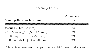
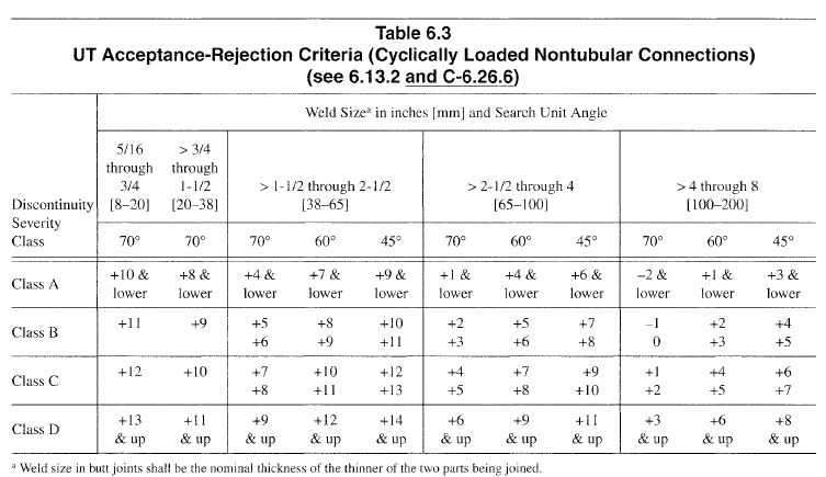
- Then Scanning dB is 65 + 19 dB scanning level is 84 dB, (19 dB from below table )
- When an Indication appears on the A scan view, the peak of the indication echo is made 50% FSH using the Gain control,
- Then record the dB level , ( in this case the indication dB level is 79dB)
- Now find the attenuation level and subtract from your dB level to find the attenuation level.
- To Find the Attenuation Level :
Attenuation = (Sound path – 1 ) x 2
Attenuation = ( 2.9 – 1 ) x 2 = 3.8 , rounded off to 4 .
Therefore , attenuation factor c= 4
Now we have:
indication dB level a=+79dB, reference level b= +65dB, attenuation factor = 4 dB
Our reference level is 65 dB
Indication rating , d =a-b-c
d = 77- 65 – 4 = 10
Actual indication level = + 10
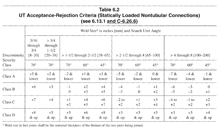
The weld joint in this case is cyclically loaded non tubular structure, so from table 6.3 below,
- + 10 and lower is found under class A rating ( ref: table 6.3)
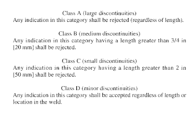
Which is rejectable regardless of length and location.
Therefore in this the Indication is rejectable
Acceptance Criteria for Ultrasonic Testing
For best Non destructive Testing Inspection services and other Material testing services in Coimbatore and NDT certification , QC training contact us at https://aqcinspection.com/
Visit our technical and career updates at our Blog site https://advancedqualitycentre.blogspot.com . https://ndtcenter.blogspot.com