Non destructive Testing (NDT)- Common Methods are:
- Visual Inspection – VT
- Liquid Penetrant Testing – LT
- Magnetic Particle Testing – MT
- Radiographic Testing – RT
- Ultrasonic Testing – UT
1. Visual Inspection – VT:
Visual inspection after welding is very useful in evaluating quality, even if other testing methods are to be employed. As welding progresses, surface flaws such as cracks, porosity, and unfilled craters can be detected only by Visual Inspections, leading to repairs or rejection of the work.
Welds must be cleaned from slag to make inspection for surface flaws possible. A 10x magnifying glass is helpful in detecting fine cracks and other faults. As indicated before, a borescope and dental mirrors, are useful for inspection inside vessels, pipe, or confined areas.
Visual inspection is the most popular and the most widely used of the non-destructive inspection techniques. Completed welds should be checked according to the plans and the specifications.
The most common welds that need to be inspected in the field are fillet welds. Fillet welds are designed based on their leg sizes. If the leg is under the specified dimension, then the strength required is less than what the joint was designed for. The throat of the weld should be checked also.
Inspector visual requirements: Performed with or without corrective lenses, to prove near vision acuity on Jaeger J2 at not less than 12 inches and a color perception test. The objective of visual inspection at this stage is not only to detect non permissible faults, but all procedure details.
If the plans show a fillet weld at 5/16 inches then each leg of the weld needs to measure to that dimension. A fillet weld gauge is the standard tool to check weld sizes.
2. Liquid Penetrant Testing – LT:
Liquid Penetrant inspection methods are used to check nonporous materials for defects open to the surface and surface defects can be found with penetrant inspection. Several types of cracks connected with seam welding, grinding, porosity or lack of bond between metals, this method can locate.
The equipment used in Liquid Penetrant Testing is portable: aerosol cans of cleaner, dye, and a developer. When fluorescent penetrant is used, a black light source in the 36-angstrom unit range and a hood or dark area are required. Portable inspection kits for field use are commercially available.
The procedure conforms to ASTM E 165. There are three types of penetrant: water washable, post emulsifying, and solvent removable. Inter-mixing these materials is not permitted.
Liquid Penetrant Testing can be done quickly and easily; it costs less per foot of weld inspected than any other nondestructive method except visual inspection. However, surface porosity and improper surface cleanliness reduce the sensitivity of the inspection technique and contaminants such as water, oil, and grease can cover or fill discontinuities so the penetrant does not enter.
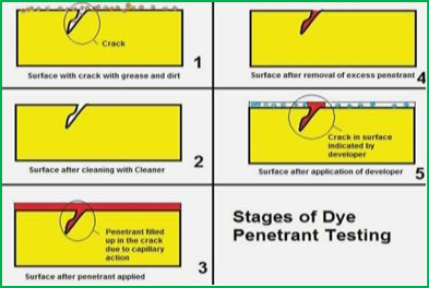
In Liquid Penetrant inspection, both visible and fluorescent, the surface of a material is coated with a film of penetrating liquid. The liquid is allowed to seep into any flaws that are open to the surface, and the excess surface film is removed.
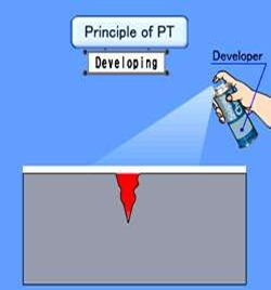
A developer is then applied; it draws the penetrant from a discontinuity to the surface so the inspector can see the flaw.
In petrochemical plants, pressure vessels and piping, which are often made of nonmagnetic materials, can be inspected for surface shallow cracks and porosity by this method. The indications for cracks and porosity bleed out rapidly upon application of the dry developer.
3. Magnetic Particle Testing – MT:
Magnetic Particle inspection is a nondestructive method of detecting cracks, seams, inclusions, segregations, porosity, lack of fusion, and similar flaws in ferromagnetic materials such as steels and some stainless steel alloys.
The main disadvantage is that it applies only to magnetic materials and is not suited for very small, deep-seated defects. The deeper the defect is, the larger it must be for detection. Subsurface defects are easier to find when they have a crack-like shape, such as lack of fusion in welds.
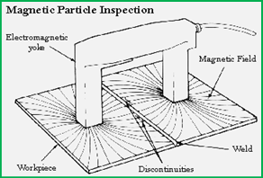
The part to be inspected is magnetized by passing through it a low-voltage, high-amperage electric current, or by placing it in a magnetic field. Electrical poles form at the ends of th e flaws. The fine magnetic particles applied to the surface of the part are attracted to these electrical poles. The concentration of particles can be seen and the flaw located.

The magnetic particles applied to the weld can be as a dry powder or as a suspension in light oil. The particles used are iron oxide particles with a proper size, shape, magnetic permeability and retentivity. They can be applied by from.
Dry particles are in powder form and may be obtained in gray, red, or black for contrast. Wet particles consist of particles suspended in a light petroleum oil or kerosene. These particles are applied using aerosol cans, dipping, immersing, hand shakers, spraying and screens.
The property of any magnetic material is to keep or retain a magnetic field after the magnetizing current is removed. Usually a magnetized metal that has high permeability has low retentivity, while a metal with a low permeability has high retentivity. Construction steels generally have low retentivity.
The particles can be colored and have a fluorescent coating for viewing with ultraviolet light. Wet particles provide better control of magnetic particles through the concentration of suspension. The wet procedure is more sensitive for the detection of extremely small discontinuities.
The procedure conforms to ASTM E 138, ASTM E 709, MIL-I-6868 and the ASME Boiler and Pressure Vessel Code, Section V. The surface should be cleaned of all grease, oil, loose rust or water because such materials interfere with the particles which indicate defects.
4. Radiographic Testing – RT:
Radiographic inspection is a nondestructive inspection technique which involves taking a picture of the internal condition of a material. This picture is produced by directing a beam of short wave- length radiation (X-rays or gamma rays) through a material that would be opaque to ordinary light.
The radioactive isotopes most widely used are Cobalt 60 and Iridium 192. Gamma rays emitted from these isotopes are similar to X-rays, except the wavelengths are usually shorter. The gamma rays penetrate to greater depths than X-rays of the same power; however, exposure times are considerably longer due to the lower intensity.
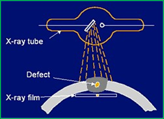
This radiation exposes a film which is placed on the opposite side of the material. When developed, the film (called a radiograph), shows the presence or absence of internal defects.
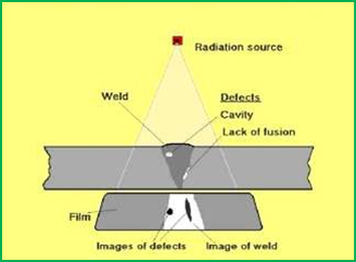
Different types of internal defects and flaws can be identified such as cracks, porosity, lack of fusion and entrapped slag. Radiography uses the penetrating power of radiation to reveal the interior of a material. Radiation from a source passes through an object and causes a change in the film emulsion when the film is developed.
The limitations, however, include high initial cost, radiation hazards, trained technicians and be aware that certain defects, particularly cracks and lack of fusion, be correctly oriented with respect to the beam of radiation (if the orientation is incorrect, the defects will not be recorded on the film).
Not all of the radiation penetrates the weld. Some is absorbed, the amount depending on the density and thickness of the weld and on the material being inspected. Inadequate technique can result in poor sensitivity, irrelevant indications, or other problems.
A cavity, such as a blowhole in the weld interior, leaves less metal for the radiation to pass through, so that the amount absorbed by the weld will vary in the defective region. These variations recorded on a radiation-sensitive film, produce an image that will indicate the presence of the defect.
The procedure conforms to ASTM E 94, ASTM E 142, and AWS D1.1. Procedures are also outlined in MIL-R-11470, MIL-STD-453, and the ASME Boiler and Pressure Vessel Code, Section V.
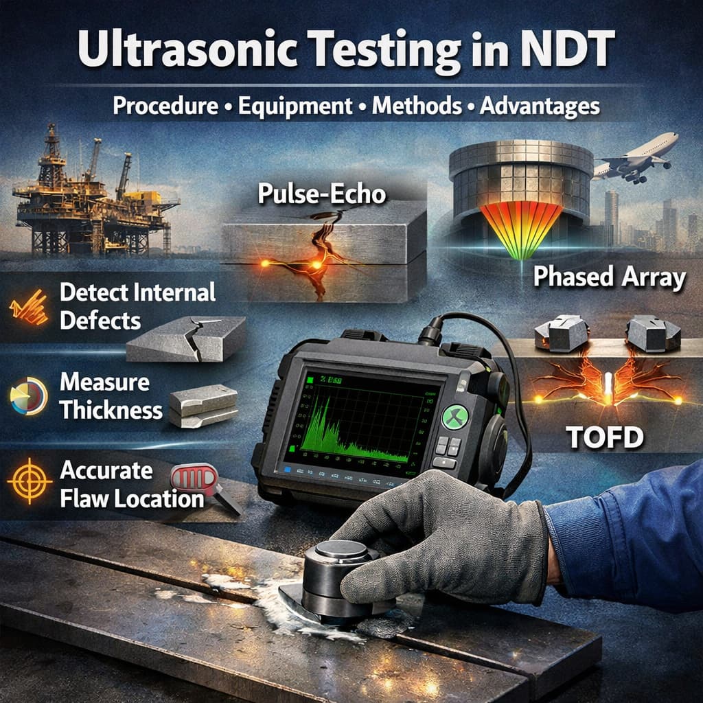
5. Ultrasonic Testing – UT:
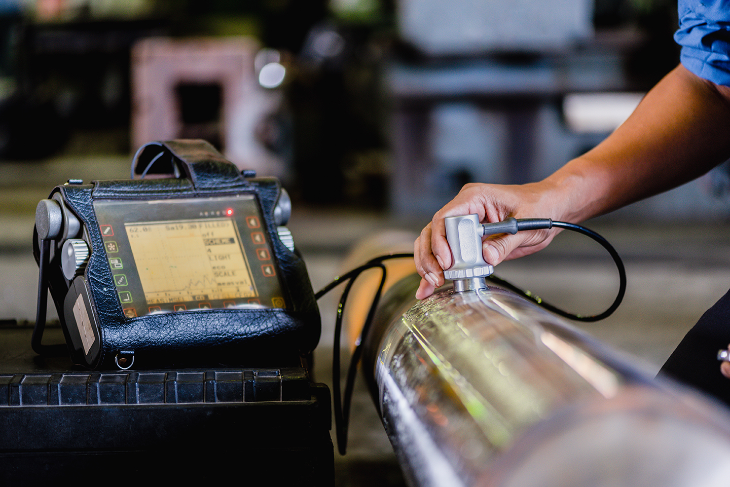
Ultrasonic inspection is an energy wave form with frequencies above 20,000 Hertz. The ultrasonic wave is introduced into the material being tested by a piezoelectric transducer placed in contact with the test specimen. The ultrasound enters the specimen and is reflected back to the transducer when it encounters an interface that could be a flaw or the back surface of the material.
The transducers consist of a straight beam and an angle beam in the frequency range of 0.1 to 15.0 MHz. The angle beam transducers that can be used are of 70°, 60° and 45°.
The ultrasonic vibrations are converted to electric signals, amplified, and displayed on a Cathode Ray Tube (CRT) screen. Because of the high frequency (above the range for the human ear), the short wave-length allows small flaws to be detected.
![]()
Ultrasonic reference blocks are usually needed to check the sensitivity and performance of ultrasonic instrumentation and transducers for inspecting critical welds. AWS D1.1 recommends several standards, the most common being the International Institute of Welding (IIW) reference blocks.
By using calibrated standards blocks and a few calculations, the inspector can classify the indications as irrelevant, acceptable, or unacceptable. Ultrasonic inspection has a higher sensitivity level than radiographic inspection.
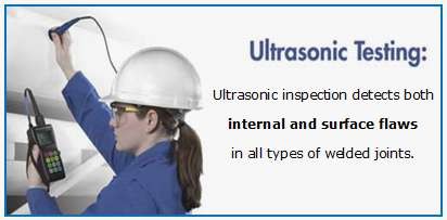
Ultrasonic inspection detects both internal and surface flaws in all types of welded joints. Defects such as slag inclusions, porosity, lack of fusion, lack of penetration (root defects), longitudinal and transverse cracks can be detected.
Indications of defects can be seen immediately on the CRT. Both internal and surface flaws can be detected, though shallow surface cracks are more easily and reliably detected with Magnetic Particle or Liquid Penetrant.
The limitations to restrict its use are the difficulty in interpreting the oscilloscope patterns and the need for standards to calibrate the instrument. A high degree of operator skill and training is required to interpret the oscilloscope patterns reliably.
The procedure conforms to ASTM E 164 and AWS D1.1. The procedures are also outlined in Appendix U to the ASME Boiler and Pressure Vessel Code, Section VIII, Division 1, and in Section V, Article 5.
Non destructive Testing (NDT)- Common Methods have different sensitivity level with few changes in them such as the chemical grain sizes, Sound frequency and many other factors. So selection of the factors affecting the sensitivity depends on the size of defects to be found. The size of defects to be found depends on the critical factor and design criteria. The designer shall decide the maximum size of defect that can be accepted considering the factors, design pressure and design wall thickness along with safety factor .
Or try to call for ‘Best NDT Technicians in Coimbatore’ and ‘Best NDT engineers near me’ to show them the drawing and design factors to select the appropriate NDT methods for finding out the defects, we can help you assisting such services find us in https://aqcinspection.com/non-destructive-testing/ we can train your employees for inspection or send you manpower and equipment for doing the inspections. You can view our blogs on NDT on https://ndtcenter.blogspot.com