Range and Sensitivity Setting for Ultrasonic testing
Setting of range and sensitivity shall be carried out prior to each testing in according to this procedure. The temprture difference between the time of range and sensitivity setting and time of test should be within ± 15°C.
Checks to confirm these settings shall be performed atleast 44 hour once and on completion of tests.
The checks should also be done whenever a system parameter is changed.
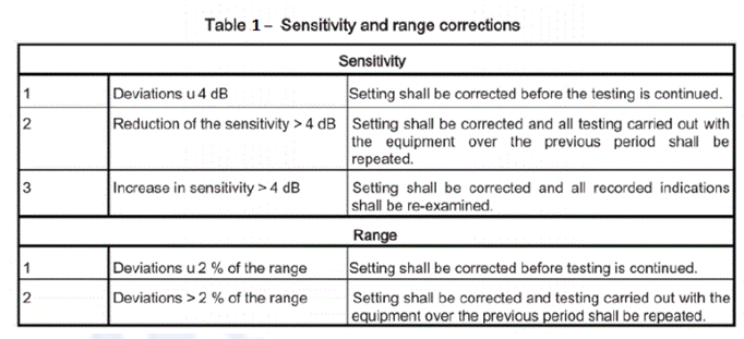
If deviations are found during these checks , corrections given in the below Table. 1 shall be carried out.
Reference for Sensitivity Setting for Ultrasonic Testing
One of the following technique shall be used for setting of reference
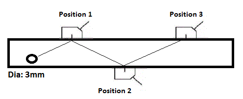
Technique 1: The reference is a Distance Amplitude Curve (DAC) from a dia 3mm side drilled hole.
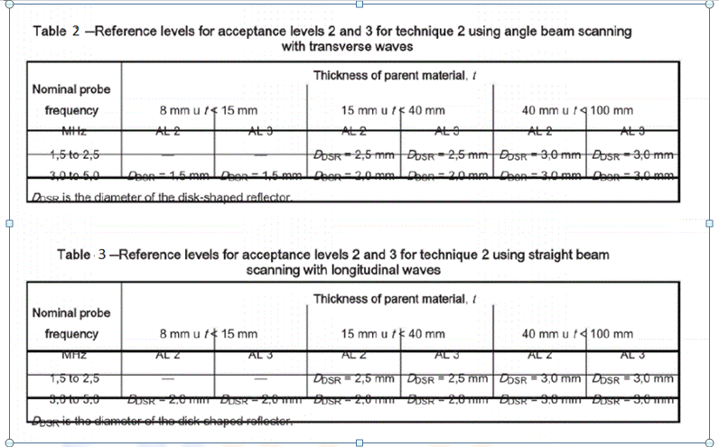
Technique 2: The references for transverse and longitudinal waves using the distance gain size technique (DGS) based on the diameter of the disk shaped reflector (DSR) are given in the table 2 & Table 3.
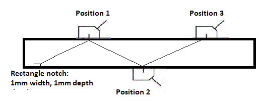
Technique 3 : The Reference notch shall be 1mm wide, rectangular with depth of 1mm . This technique applies only for thickness range 8mm u t<15mm and fr beam angles W 70°.
Technique 4 : For the tandem technique, the reference is a flat bottom hole of 6mm diameter (for all thickness), perpendicular to scanning surface. This technique is applicable only beam angle 45° and thickness tW 15mm .
The length of the side drilled hole and notches shall be greater than the width of the sound beam measured at -20 dB .
Transfer Correction
When separate reference block is used for establishing reference levels, a measurement be made for transfer differences.
Step 1 : Set the echo reflected from a corner of the reference block at 80% of full screen height . The decibal dB required for the setting is noted, Db reference.
Step 2 : Set the echo reflected from a corner of the test weld material at 80% of full screen height . The decibal dB required for the setting is noted , Db Test.
Step 3 : The Difference between two values , Db reference – Db Test = Transfer Correction.
- If the difference is less than 2dB, then the correction is not required.
- If the difference is more than 2dB and less thaan 12 dB, then the compensation is given to the machine.
- If the transfer loss exceeds 12dB , the reason shall be considered and further preparation of the scanning surfaces shall be carried out , if applicable.
- When there is no apparent reasons for high correction values, the attenuation at various locations on the test object shall be measured and where it is found to vary significantly, corrective actions shall be considered.
Sound to Noise ratio
During testing of weld, the noise level, excluding spurious surface indications, shall remain at least 12 dB below the evaluation level . This requirement may be relaxed subject to specification.
For more detail of Ultrasonic testing services and other NDT services feel free to contact us at https://aqcinspection.com/ for best services.
Visit our technical and career updates at our Blog site https://advancedqualitycentre.blogspot.com . https://ndtcenter.blogspot.com our website https://aqcinspection.com/news-events/ for many more blogs